A milled inside corner always has a radius, because the cutter is round. The drawing should say how large that radius may be, whether a corner relief is allowed where a square part has to fit, and which few corners really need wire EDM or sinker EDM. This article explains how to choose the radius, when to use a relief, and how to state it clearly on your drawing.
Why Milled Inside Corners Are Always Round
An end mill cuts with its side, and its side is a circle. Where two milled walls meet, the corner takes the radius of the cutter: a 6 mm end mill leaves about 3 mm, a 2 mm end mill about 1 mm. Smaller radii need smaller cutters, which are slower, less rigid and cannot reach as deep, so the corner radius directly affects machining time and cost.
Three kinds of inside corner are specified differently:
- Vertical corners, where two side walls meet. Their radius comes from the cutter diameter.
- Floor corners, where a wall meets the floor of a step or pocket. With a flat end mill they can be nearly sharp.
- Through corners of slots or openings that go right through the part. These can be milled with a radius or cut by wire EDM with a much smaller one.
Choosing the Corner Radius
If nothing square has to sit in the corner, a generous radius is the cheapest and strongest option. Common CNC design guidance suggests:
- At least one third of the wall depth. Hubs gives the example of a 12 mm deep cavity with a radius of 5 mm or more, which lets an 8 mm cutter do the work (Hubs).
- Slightly larger than the cutter radius, so the tool moves through the corner in an arc instead of being heavily loaded.
- One radius for all inside corners where possible, to avoid extra tools.
- Small or no floor radii, such as 0.5 mm or 1 mm, unless you need them for strength (Hubs).
On parts hardened after machining, a radius at the root of a step also reduces the risk of cracking, so it often helps the part as well as the cost.
When a Square Part Has to Fit: Corner Reliefs
If a corner must accept a part with sharp outer corners, such as a ground insert or a block that sits against both walls, a milled radius stops it from seating. The usual solution is a corner relief that removes material beyond the corner:
- T-bone relief: the cutter goes past the corner along one wall, keeping the other wall clean. It only needs to extend by at least one cutter radius (Get It Made).
- Dog-bone relief: the cutter goes diagonally into the corner and clears both walls. An offset version removes less material than a circle centred on the corner (Get It Made).
- Undercut at a step: a small groove at the root lets a part sit flat on the floor and against the wall.
State the largest relief you can accept, or mark the relief as allowed, and check that it does not break into a hole or a thin wall.
When the Corner Must Really Be Sharp: Wire EDM and Sinker EDM
- Wire EDM cuts features that go right through the part. The smallest inside radius is roughly the wire radius plus the discharge gap; PCBWay gives the example of a 0.2 mm wire producing about 0.13 mm, and notes that a zero radius cannot be made (PCBWay). See wire EDM for punches and die inserts.
- Sinker EDM makes small corners in blind features where a wire cannot pass. See sinker EDM for mold and die components.
EDM adds an operation, so mill the corners with a normal radius and mark only the functional ones with a maximum radius.
Outside Edges Are a Separate Question
Outside edges are normally deburred or given a small chamfer. ISO 13715 gives a way to state the condition of edges whose shape is not drawn: a minus value means material must be removed (such as a chamfer on an outside edge), and a plus value means extra material is allowed (such as a small fillet in an inside corner) (Modulus Metal, ISO 13715 overview). If you use a general edge note, make sure it also covers inside corners.
How to Show Inside Corners on the Drawing
| Situation | Example note or callout |
|---|---|
| General rule for milled corners | UNLESS OTHERWISE SPECIFIED, INSIDE CORNERS R1 MAX |
| Radius not critical | INSIDE CORNER RADII AT SUPPLIER’S OPTION, R5 MAX |
| Corner that must take a square part | CORNER RELIEF ALLOWED, Ø4 MAX |
| Step where a part must sit flat on both faces | UNDERCUT AT ROOT OF STEP ALLOWED, 0.5 × 0.5 MAX |
| Functional sharp corner in a through feature | R0.15 MAX (WIRE EDM) |
| Outside edges | BREAK ALL SHARP EDGES 0.2–0.5, or an ISO 13715 edge note |
These values are examples. Say whether a value is a maximum or a nominal size: “R1 MAX” allows any radius up to 1 mm, while “R1” with the general tolerance is nominal. If you send only a 3D model with sharp inside corners and no note, the radius is undefined, so model it or add a note.
Checklist Before You Send the Drawing
- A general note for inside corner radii, stating maximum or nominal.
- Vertical radii at least about one third of the wall depth where possible, and the same radius on most corners.
- A relief shown or allowed wherever a square part must fit.
- Only truly functional corners marked with a small maximum radius for EDM.
- A separate note for outside edges.
How We Machine Steps, Slots and Inside Corners
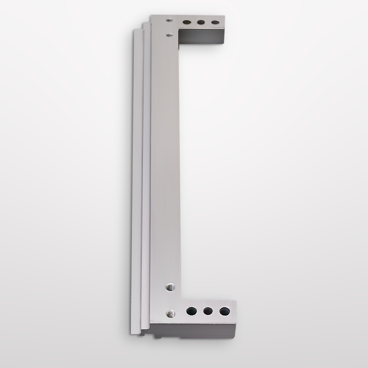
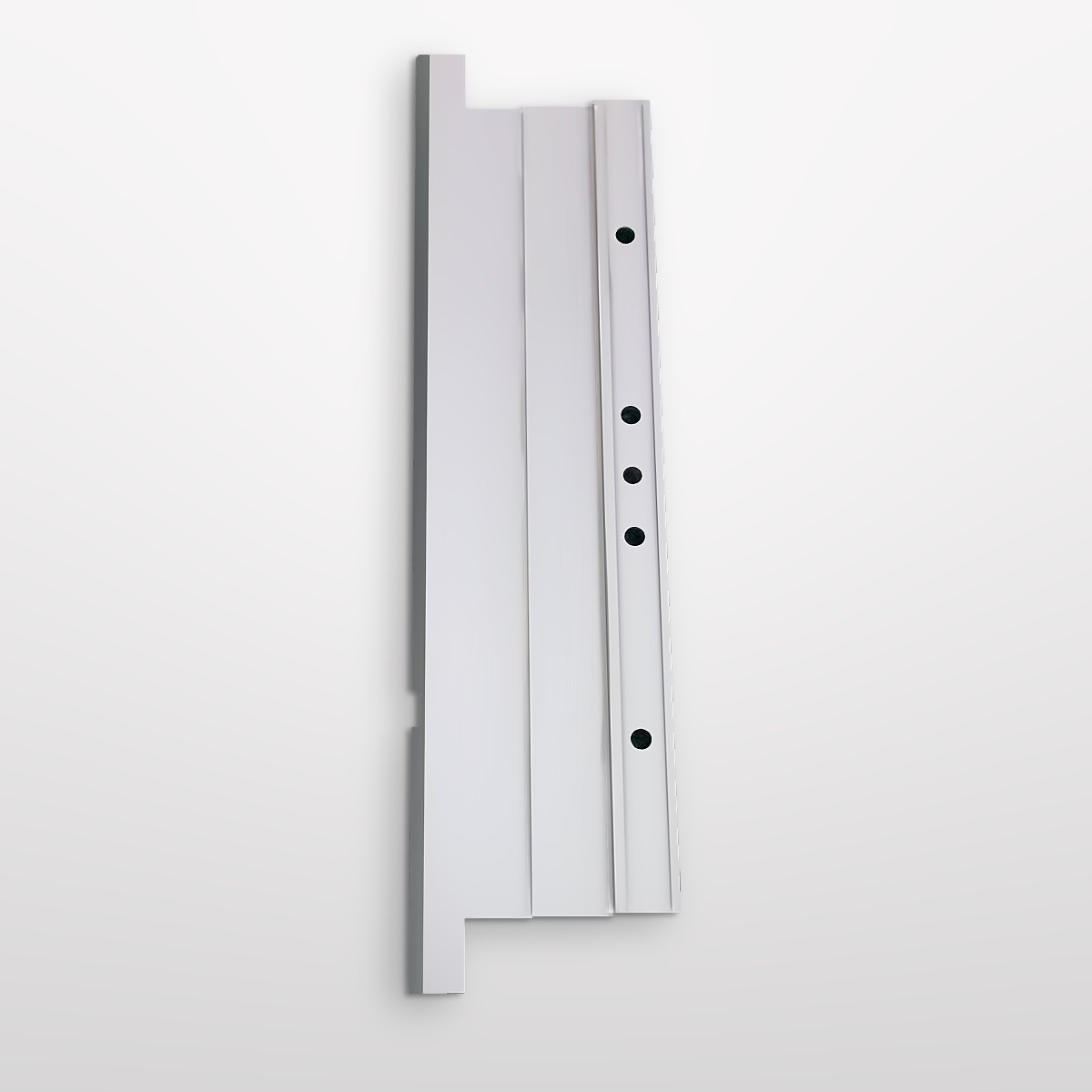
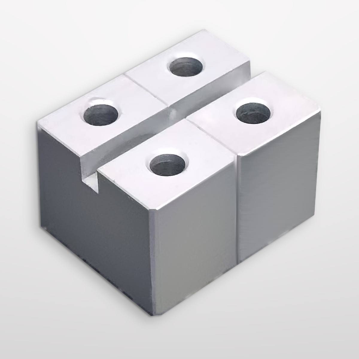
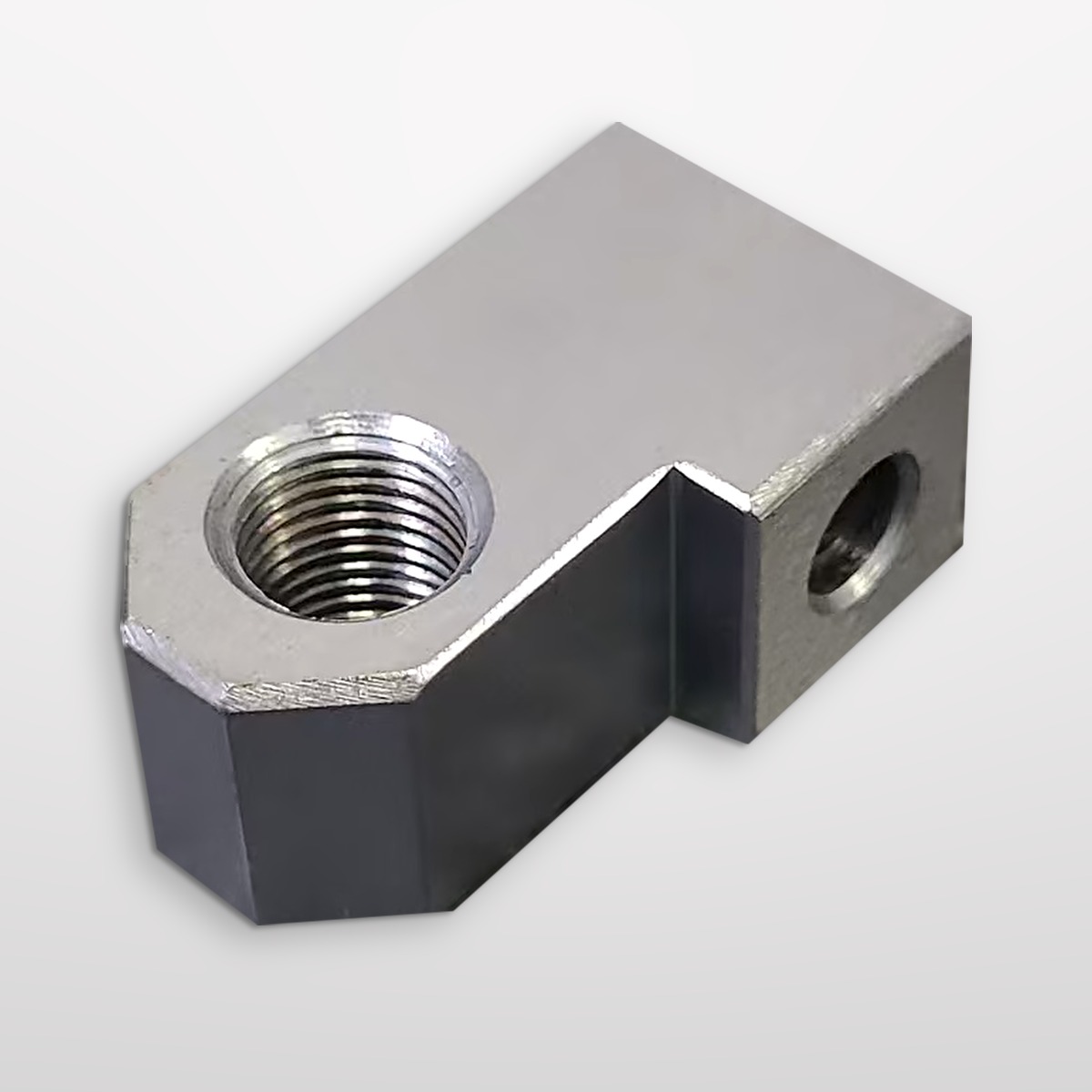
At SkyPu, we make CNC machined parts and stamping die components to customer drawings, including fixture blocks, brackets, stepped plates and die plates. Steps, slots and pockets are milled on our 8 CNC machining centers, and openings that need small inside radii are cut on our 18 wire EDM machines, including Sodick low-speed wire EDM. Critical dimensions are checked with Nikon and TESA inspection equipment, and a dimensional report can be supplied on request. Selected features can be held to approximately ±0.002 mm. You can see examples in our CNC milling product cases and stamping tooling product cases. If a corner on your drawing would be cheaper with a different radius or a relief, we will point it out when we quote.
Frequently Asked Questions
Can you mill a perfectly sharp inside corner?
No. A milled vertical inside corner always has a radius at least equal to the cutter radius. Use a corner relief for square mating parts, or wire EDM or sinker EDM for very small radii.
What inside corner radius should I put on my drawing?
The largest your design allows: typically at least one third of the wall depth, slightly larger than the cutter radius, and the same on all corners where possible.
How small can a wire EDM inside corner be?
Roughly the wire radius plus the discharge gap, for example about 0.13 mm with a 0.2 mm wire. Give a maximum radius instead of a sharp corner.
Need fixture blocks, brackets or stepped plates made to drawing? Send your drawings with material, quantity and any critical corners marked, and we will review it and reply with a price and lead time.
Sources
- Hubs: Reducing CNC machining costs, design tips (internal corner radii and cavity depth)
- Get It Made: Machining square corners with CNC milling (fillets, dog-bone and T-bone reliefs)
- PCBWay: EDM design guidelines (wire EDM minimum inside corner radius)
- Wikipedia: Rule-based DFM analysis for electric discharge machining
- Modulus Metal: ISO 13715, edges of undefined shape, indication and dimensioning