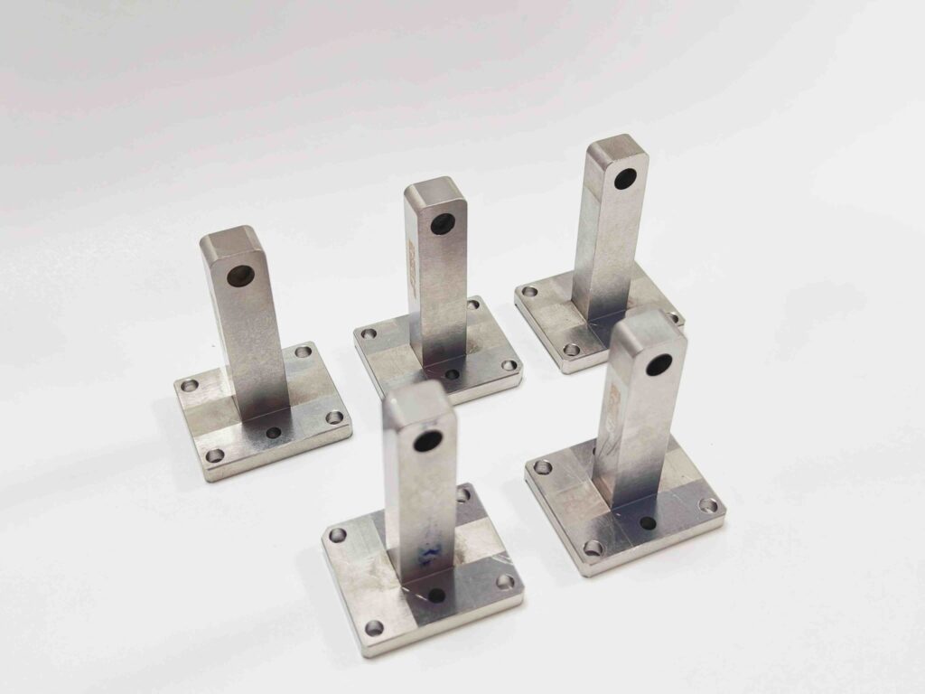
Wire EDM is the process behind many of the most demanding features in stamping and mold tooling: punch profiles, die openings, narrow slots, sharp-cornered inserts and hardened parts that cannot be milled economically. Because the process cuts with electrical discharges rather than a cutting tool, it can hold close tolerances in fully hardened tool steel and tungsten carbide. But a drawing that only says “wire cut” leaves several important decisions open, and those decisions affect accuracy, edge quality, tool life and price.
This guide explains what buyers of punches, die inserts and mold components should specify when a part depends on wire EDM, so the supplier can choose the right machine, cutting strategy and inspection method before quoting.
How Wire EDM Works, in Brief
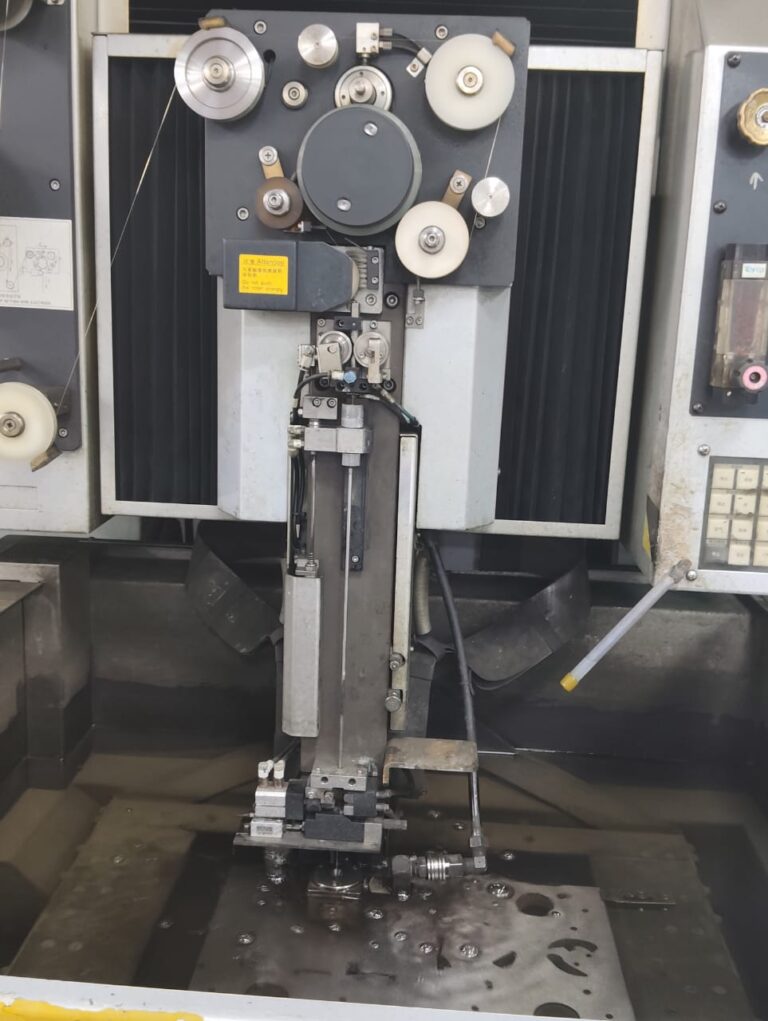
In wire electrical discharge machining, a thin, electrically charged wire travels through the workpiece while it is submerged in, or flushed with, a dielectric fluid. Controlled sparks between the wire and the workpiece erode material along the programmed path. The wire never touches the part, so there is no cutting force, and the hardness of the material does not limit the process. The workpiece must, however, be electrically conductive.
Because of this, wire EDM is well suited to:
- Punch and die profiles for progressive and compound stamping dies
- Die inserts, stripper inserts and cutting blocks with complex outlines
- Narrow slots, fine pitches and comb-type features, such as those used in connector tooling
- Mold inserts, core components and ejector-related parts with sharp internal geometry
- Parts cut after heat treatment, where milling or turning would be slow or impractical
Low-Speed Wire EDM vs. Reciprocating Wire EDM
When sourcing from China, it helps to know that “wire cutting” can refer to two different classes of machine.
Low-speed (single-pass) wire EDM, often called slow-wire, feeds a fresh brass or coated wire through the cut once and then discards it. These machines use precision guides, tightly controlled generators and usually several finishing passes. They are the standard choice for precision tooling where profile accuracy, surface finish and edge condition matter.
Reciprocating wire EDM, known locally as fast-wire or medium-wire, runs a molybdenum wire back and forth repeatedly. These machines are economical and useful for roughing, fixtures and less critical parts, but they generally cannot match low-speed machines for accuracy, surface finish or consistency across a batch.
Both processes have a place. The point for a buyer is that two quotes for the same “wire-cut” punch may be based on different machines. If the punch-to-die clearance, cutting edge or surface finish is critical, state that the profile must be cut on low-speed wire EDM, or state the finish and tolerance requirements clearly enough that the supplier cannot meet them any other way.
Skim Cuts: Where Accuracy and Edge Quality Come From
The first pass of a wire EDM cut, the main cut, removes material quickly but leaves a rougher surface and a heat-affected layer. Precision parts are then finished with one or more skim cuts (trim cuts), in which the wire passes along the same profile at lower energy, removing a small amount of material each time.
Each additional skim cut typically:
- Improves dimensional accuracy and corrects small deviations from the main cut
- Produces a finer surface finish
- Reduces the thickness of the recast layer left by the discharges
- Adds machine time, and therefore cost
For a cutting punch or die opening, the condition of the cut surface directly affects burr formation and tool life. A drawing that specifies the required surface finish on the cutting faces, or the number of skim passes your toolroom expects, gives the supplier a clear basis for the cutting strategy and avoids a quote built on the cheapest acceptable interpretation.
The Recast Layer and Why It Matters
Every EDM spark melts a tiny volume of material. Some of it resolidifies on the surface as a thin recast layer (sometimes called the white layer), with a heat-affected zone beneath it. On a main cut this layer is thicker and can contain microcracks. On a well-executed finishing sequence it becomes very thin.
For cutting edges and highly loaded tooling, a thick recast layer can promote edge chipping and shorten tool life. Where this matters, buyers can:
- Require finishing skim cuts on functional surfaces
- Specify grinding or polishing after wire EDM on critical faces
- Ask how the supplier controls the recast layer on cutting edges
Wire EDM of Tungsten Carbide
Tungsten carbide punches and inserts are widely used where wear resistance is the priority. Carbide can be cut by wire EDM, but it needs more care than tool steel. Carbide grades consist of hard tungsten carbide grains held together by a cobalt binder. In water-based dielectric, electrolytic effects can draw cobalt out of the surface layer, leaving it weaker and more prone to chipping.
Suppliers manage this with machines and generators designed to reduce electrolysis, appropriate cutting conditions, and finishing passes or grinding to remove the affected surface. When ordering carbide components, it is worth confirming the carbide grade, how the critical profile will be finished, and whether the cutting edges will be ground after EDM. Our article on tool steel vs. carbide for stamping die components covers the material choice itself.
Heat Treatment Before Cutting
One of the main advantages of wire EDM is that it can cut hardened material. For tool steel punches and inserts, the usual sequence is to rough machine the blank, heat treat it to the specified hardness, and then wire cut and grind the finished geometry. This avoids the size change and distortion that heat treatment would otherwise introduce into a finished profile.
Large blocks can still move during cutting as internal stresses are released. Common countermeasures include stress relieving, pre-cutting the profile with stock allowance before the finish cut, and drilling start holes so the profile is cut from inside the block rather than in from an edge. The drawing should state the required hardness and, where relevant, whether the profile must be finished after heat treatment.
Geometry Limits to Design Around
Wire EDM is flexible, but the wire itself sets some limits:
- Internal corner radius. An internal corner can be no sharper than the wire radius plus the spark gap. Finer wire allows smaller radii but cuts more slowly. If a sharp internal corner is functionally necessary, say so, so the supplier can select the wire size or an alternative process.
- Through features only. The wire must pass through the part. Blind pockets and cavities need sinker EDM or milling instead.
- Start holes. Closed internal profiles need a start hole for threading the wire. If the location of that hole matters, show it on the drawing.
- Taper and land. Die openings often need a straight land followed by a relief taper. Specify the land length and the taper angle rather than leaving them to interpretation.
- Thickness. Very thick sections cut more slowly and are more sensitive to flushing conditions, which can affect straightness.
What to Include in Your RFQ
For wire EDM punches, die inserts and mold components, a complete request for quotation should include:
- A dimensioned 2D drawing and a 3D model, with the current revision
- Material grade, including the carbide grade for carbide parts
- Required hardness and any heat-treatment or coating requirements
- Profile tolerance, and punch-to-die clearance where the punch and die are made together
- Surface finish requirements on cutting edges and functional faces
- Internal corner radii and any features that must be sharp
- Land length and relief taper for die openings
- Whether grinding or polishing is required after wire EDM
- Quantity, including spare or replacement components
- Inspection requirements, such as a dimensional report or a first article inspection
For replacement components, also see what to include in an RFQ for replacement punch and die components. For inspection documentation, see our guide to first article inspection.
How SkyPu Approaches Wire EDM Tooling Components
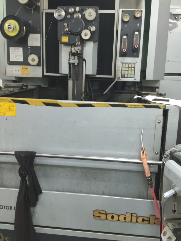
At SkyPu, precision profiles are cut on Sodick low-speed wire EDM machines, used alongside CNC milling, grinding and sinker EDM to manufacture stamping die components and precision mold components to customer drawings. Before quoting, our engineers review the material, hardness, critical profiles and finish requirements, and plan the sequence of rough machining, heat treatment, wire cutting and grinding to suit the part. Critical dimensions are measured with Nikon and TESA inspection equipment, and dimensional reports are available on request.
If you have a punch, die insert or mold component that depends on wire EDM, send us your drawing with the material, hardness, quantity and any finish requirements, and our team will review it and reply with a quotation.