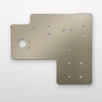

Die plates, stripper plates, punch holder plates, inserts, guide rails and spacer blocks all depend on the same thing: faces that are flat, parallel and at the right thickness. In most toolrooms those faces are produced by surface grinding, usually after heat treatment. A drawing that simply says “grind all over” leaves the supplier to decide how flat, how parallel and how smooth the part needs to be, and those decisions affect fit, tool life and cost.
This guide explains what surface grinding does well, where problems come from, and what to state on the drawing and in the RFQ when ordering ground tooling components.
What Surface Grinding Does
On a reciprocating surface grinder, the workpiece is held on a table, usually by a magnetic chuck, and passed back and forth under a rotating abrasive wheel. Each pass removes a very small amount of material, and coolant carries away heat and swarf. Because the cut is light and the machine is rigid, surface grinding can produce flat, parallel faces with a fine finish on materials that are too hard to mill economically, including fully hardened tool steel.
For tooling components, surface grinding is typically used to:
- Bring plates and blocks to final thickness after heat treatment
- Make the top and bottom faces of a plate parallel to each other
- Grind reference edges square to the main faces, so the part can be located accurately in a die set or fixture
- Produce a consistent surface finish on functional and seating faces
- Match the height of components that must sit at the same level, such as punches, inserts or spacer blocks in one set

Flatness, Parallelism and Thickness Are Different Requirements
These three terms are often used loosely, but they control different things, and a part can meet one while failing another.
Flatness controls the form of a single surface. It is defined as a zone between two parallel planes that the whole surface must fit within. It does not refer to any other feature.
Parallelism controls the orientation of one surface relative to a datum, usually the opposite face. A plate can be flat on both sides but still be thicker at one end than the other, which is a parallelism problem.
Thickness is a size tolerance measured between the two faces. A plate that is within thickness everywhere is not necessarily flat or parallel to a tighter requirement, because the size tolerance may be wider than the form tolerance you actually need.
For stack-ups in a die set, where several plates sit on top of each other, parallelism and thickness usually matter most. For seating faces, where an insert or plate must sit fully on a mating surface, flatness is often the key requirement. Stating each one with a geometric tolerance and a clear datum gives the supplier an unambiguous target and an inspection method.
Squareness and Six-Face Grinding
Blocks, inserts and stops often need more than two ground faces. When a part must be located from its edges, specify which faces are datums and the perpendicularity required between them. Grinding all six faces of a block square to each other takes additional setups and time, so it is worth stating where it is genuinely needed rather than applying it to every surface by default.

Distortion, Stress and the Magnetic Chuck
Most grinding problems in tooling plates come from stress rather than the grinding wheel itself.
Heat treatment, earlier machining and the release of stresses during material removal can all leave a plate slightly bowed. A magnetic chuck pulls a thin plate flat while it is being ground. When the magnet is switched off, the plate can spring back towards its original shape, so the ground face measures flat on the machine but not on the inspection table.
Experienced grinders manage this by:
- Removing material evenly from both sides and turning the part over several times
- Taking lighter finishing passes so the part is not heated unevenly
- Supporting a bowed plate so it is not pulled flat by the chuck during the first passes
- Leaving enough grinding allowance after heat treatment to clean up any distortion
- Demagnetizing parts after grinding, which matters for components that must not attract chips or interfere with sensors
For thin plates with tight flatness requirements, it helps if the drawing shows the material, the hardness and whether the part will be heat treated before final grinding, so the supplier can plan a suitable allowance and sequence.
Grinding Hardened Steel Without Damaging It
Grinding generates heat at the point of contact. If the wheel is unsuitable, worn or pushed too hard, the surface of hardened tool steel can overheat. This “grinding burn” may show as discoloration, but it can also change the hardness of the surface layer or cause fine cracks that are not visible without inspection. On cutting edges and highly loaded faces, that damage can shorten tool life.
The usual countermeasures are an appropriate wheel for the material, a properly dressed wheel, sufficient coolant and light finishing cuts. Highly alloyed tool steels and harder materials may call for different abrasives from those used on mild steel. For tungsten carbide, diamond wheels are used. Our article on tool steel vs. carbide for stamping die components covers the material choice itself.
Non-Magnetic Materials
Aluminum, copper alloys, austenitic stainless steels and carbide are not held by a magnetic chuck. These parts need another workholding method, such as a vacuum chuck, a fixture or a magnetic-chuck setup with blocking. Workholding affects both setup time and the achievable result, so the material should always be stated clearly in the RFQ.

Surface Finish
Surface grinding generally produces a finer finish than milling, and the finish depends on the wheel, the dressing and the final passes. If a face is functional, for example a sliding face, a seating face or a sealing face, specify the required roughness with a value such as Ra on that face. If not, a general note is usually enough. Asking for a very fine finish on every face adds time without improving the part.
How Ground Faces Are Inspected
Each requirement has its own inspection method, which is another reason to state them separately:
- Thickness is measured with micrometers or a height gauge at several points across the part.
- Parallelism is checked by placing the part on a reference surface, such as a granite surface plate, and measuring the variation of the opposite face with an indicator.
- Flatness is checked against a reference surface or measured on a coordinate measuring machine, depending on the size of the part and the tolerance.
- Squareness is checked with a square, an indicator setup or a CMM.
- Surface roughness is measured with a roughness tester on the specified faces.
If you need a record of these results, ask for a dimensional report or a first article inspection report when you request the quotation, not after the parts have shipped.
What to Include in Your RFQ
For ground plates, blocks and inserts, a complete request for quotation should include:
- A dimensioned 2D drawing and a 3D model, with the current revision
- Material grade and required hardness
- Whether the part is heat treated before final grinding
- Thickness tolerance, and flatness and parallelism with their datums
- Squareness requirements for edges that are used for location
- Which faces must be ground, and which can be left as milled
- Surface roughness on functional faces
- Any requirement for demagnetizing
- Quantity, including spares and matched sets
- Inspection documentation, such as a dimensional report
When comparing offers, check that each supplier has quoted the same grinding scope. Our guide to comparing CNC machining quotes explains what else to look for beyond the unit price, and our article on material certificates covers material documentation.
How SkyPu Handles Ground Tooling Components
At SkyPu, surface grinding on our Chevalier FSG-1632ADIV CNC surface grinder is used together with CNC milling, wire EDM and sinker EDM to manufacture stamping die components, precision mold components and fixture parts to customer drawings. Before quoting, our engineers review the material, hardness and the flatness, parallelism and finish requirements, and plan the sequence of rough machining, heat treatment and grinding to suit the part. Critical dimensions are measured with Nikon and TESA inspection equipment, and dimensional reports are available on request.
If you have plates, blocks or inserts that need precision grinding, send us your drawing with the material, hardness, quantity and tolerance requirements, and our team will review it and reply with a quotation.