
A drawing that says only “clearance 10%” leaves the toolmaker guessing. Is that 10% per side or in total? Does the punch or the die carry the nominal size? A wrong guess shows up later as burrs, oversized or undersized holes and punches that wear out early. This article gives reference clearance values by material and shows how to write clearance on a drawing so that your punch and die supplier makes exactly what you need.
What Punch and Die Clearance Does
Clearance is the gap between the cutting edge of the punch and the cutting edge of the die opening. It is normally given per side, as a percentage of the sheet thickness.
When the punch enters the sheet, the cut edge forms in stages: a small rollover where the material is pulled in, a smooth burnished band where it is sheared, and a rougher fracture zone where it breaks. A burr forms on the side where the material leaves the cutting edge. With the right clearance, the cracks from the punch edge and the die edge meet cleanly, cutting force is low and tool life is long (Mate).
- Too tight: a large burnished band and a near-vertical edge, and tool life is reduced (Mate). Punching and stripping forces go up, and very tight clearance can cause secondary shear, a second shiny band on the edge (PMA).
- Too loose: a large rollover, a rough fracture zone and a thin burr. Tool life is also reduced (Mate).
For many years a single value of 5% per side was used as a rule of thumb for all materials and thicknesses. Tooling makers now recommend choosing clearance by material strength and thickness instead (Dayton Lamina).
Reference Clearance Values by Material
The table below is taken from MISUMI’s technical data for piercing punches. It gives two grades: a precision grade (P), which leaves a sheared (burnished) surface of about 50% of the thickness, and a standard grade (S), which leaves 30% or less and is easier on the tools.
| Work material | Condition | Precision grade P (% of thickness, per side) | Standard grade S (% of thickness, per side) |
|---|---|---|---|
| Aluminum alloy | Soft | 3 | 6 |
| Aluminum alloy | Medium | 4 | 8 |
| Aluminum alloy | Hard | 8 | 10 |
| Copper (tough pitch) | Soft | 6 | 8 |
| Copper (tough pitch) | Hard | 8 | 10 |
| 真鍮 | Soft | 4 | 8 |
| 真鍮 | Hard | 8 | 10 |
| Phosphor bronze | Soft | 6 | 10 |
| Phosphor bronze | Hard | 10 | 15 |
| スチール | Extra soft | 6 | 10 |
| スチール | Soft | 10 | 12 |
| スチール | Hard | 12 | 15 |
| Stainless steel | Soft | 6 | 12 |
| Stainless steel | Hard | 8 | 15 |
| Silicon steel | — | 8 | 12 |
Source: MISUMI, clearance selection for piercing punches. MISUMI’s engineers also give about 10% per side as a common starting point, with 11–20% per side used to reduce tool strain when piercing (MISUMI blog). Treat these numbers as starting values; your own part quality and tool life records are the final reference.
How to Turn the Percentage into Punch and Die Sizes
Clearance per side = sheet thickness × clearance %. Because the gap is on both sides of a round or closed shape, the die opening is larger than the punch by twice that amount.
Which part keeps the nominal size depends on which part of the strip you are keeping:
- Piercing (the hole is the feature): the punch is made to the hole size, and the die opening is larger. Example from MISUMI: 1.6 mm sheet, 10% per side, so clearance = 0.16 mm. A 6.00 mm punch needs a 6.00 + 2 × 0.16 = 6.32 mm die hole.
- Blanking (the slug is the part): the die opening is made to the part size, and the punch is smaller. With the same sheet and clearance, a 20.00 mm blank needs a 20.00 mm die opening and a 20.00 − 0.32 = 19.68 mm punch.
The clearest drawings state the result as dimensions with tolerances, not only as a percentage. A note such as the one below removes most of the questions a toolmaker would otherwise ask:
Material: SPCC, t = 1.6 mm. Piercing. Punch Ø6.00 (0/−0.005). Die opening Ø6.32 (+0.005/0). Clearance 0.16 mm per side (10% of t), uniform around the profile.
If you can only give a percentage, write “per side” or “total” next to it every time. Some tooling catalogs quote total clearance, for example 20% total for thick plate (Roper Whitney), so the same number can mean two different die sizes.
Have a drawing for a punch, die insert or die plate like this? Send it to us and we will reply with a price and lead time within 2 days.
Common Clearance Problems and How to Avoid Them
- Burr higher than allowed. Cause: in most cases, worn cutting edges. Burr height is the main sign of tool wear, and more clearance does not by itself mean a higher burr (Dayton Lamina). Avoid it by stating a maximum burr height on the part drawing, keeping spare punches and regrinding before the limit is reached.
- Second shiny band on the cut edge. Cause: secondary shear from clearance that is too tight. It also raises punching and stripping forces (PMA). Avoid it by moving toward the standard-grade value for that material.
- Hole size slightly off. Cause: clearance changes the hole size. Tight clearance can make the hole up to 0.0005 in (about 0.013 mm) smaller than the punch, and larger clearance can make it 0.0002–0.0005 in (about 0.005–0.013 mm) larger (Dayton Lamina). Avoid it by tolerancing the hole on the part drawing and letting the toolmaker size the punch.
- Large rollover where a tapped or formed hole is needed. Cause: clearance too large (Dayton Lamina). Avoid it by marking those holes as critical so they get a tighter, precision-grade clearance.
- Burr on one side of the hole only. Cause: the clearance is not even around the profile because the punch and die opening are misaligned. Avoid it by specifying the position tolerance between the punch, the punch plate and the die opening, and by having the punch and the die opening made from the same CAD data.
- Die made to the wrong size. Cause: “10%” read as total instead of per side, or the clearance applied to the wrong part. Avoid it by giving both punch and die sizes, as in the example note above.
Clearance also affects how fast a punch wears. Dayton Lamina reports that larger, engineered clearance can reduce abrasive punch wear by as much as two-thirds, and that raising clearance from 6% to 14% per side cut the piercing load by about 10% in one test (Dayton Lamina). Our article on tool steel vs carbide die components covers the other half of tool life: the punch material.

What to Include in Your Drawing and RFQ
- Strip material grade, temper or hardness, and thickness with its tolerance
- Whether each feature is pierced or blanked, so it is clear which part carries the nominal size
- Clearance as punch and die dimensions, or as a percentage marked “per side” or “total”
- Maximum burr height and the side the burr may be on
- Critical holes that will be tapped, formed or used for location
- Punch and die material and required hardness, for example SKD11 tool steel or carbide
- Quantity, including spare punches, and whether parts are replacements for an existing die
- CAD files (DXF or STEP) together with the PDF drawing
For replacement parts, our guide to quoting replacement punch and die components lists what to send when the original drawing is missing.
How We Make Punches and Die Openings
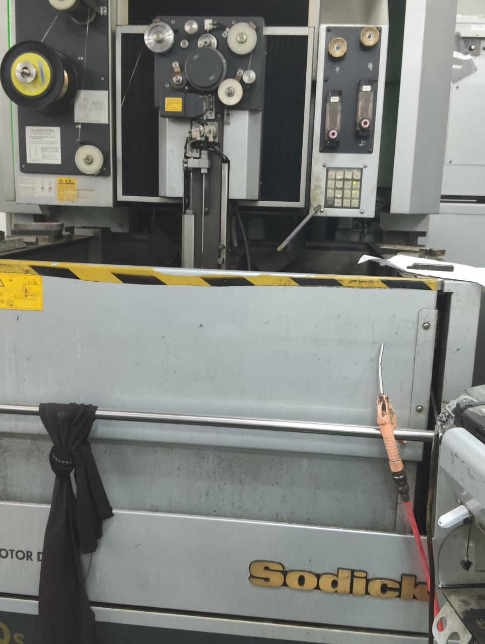
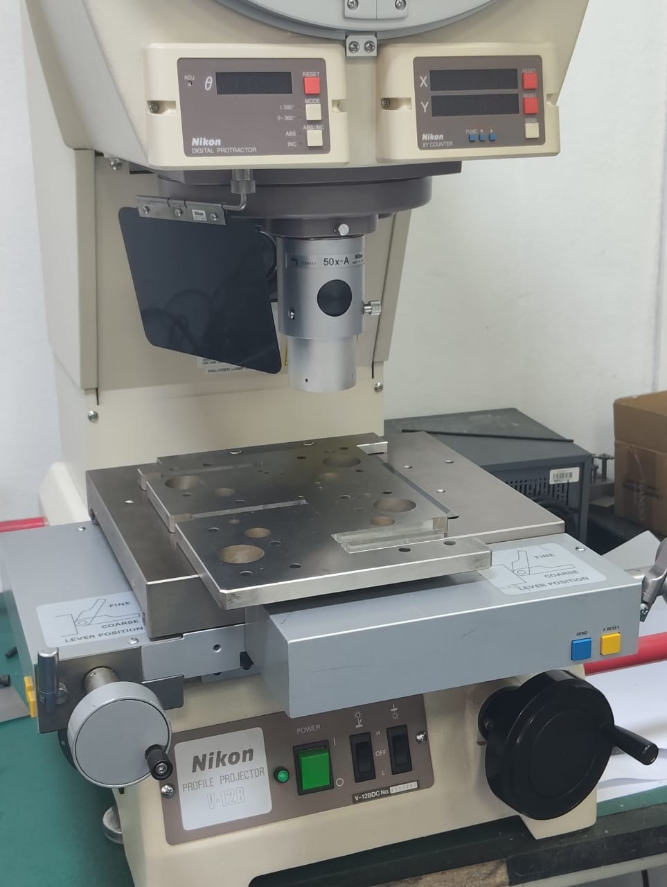
At SkyPu, we manufacture stamping die components to customer drawings: punches, die inserts, die plates, stripper plates and punch holders. Die openings and shaped punches are cut on our 18 wire EDM machines, including Sodick low-speed wire EDM, and finished by surface grinding where flatness or height matters. Profiles and clearances are checked on a Nikon V-12B profile projector and a Nikon MM-400 measuring microscope. We machine to tolerances down to ±0.002 mm, and typical lead time is about one week, excluding shipping. More detail on the machining side is in our article on wire EDM punches and die inserts, and on inspection in our profile projector article.
よくある質問
Is punch and die clearance given per side or in total?
MISUMI and Dayton Lamina give clearance per side, but some tooling suppliers quote total clearance. Always write “per side” or “total” on the drawing, or give the punch and die sizes directly.
Can you make the die if I only give a clearance percentage?
Yes, if we also know the strip material, its thickness and whether the feature is pierced or blanked. From that we can work out the punch and die sizes and send them to you to confirm.
Which clearance should I choose for stainless steel?
MISUMI’s table gives 6–8% per side for a precision cut and 12–15% per side for standard cutting, depending on hardness. If you are not sure, tell us the burr limit and the expected volume, and we can propose a value.
How long does it take to make a replacement punch and die set?
Typical lead time is about one week, excluding shipping. We confirm the lead time for your parts with each quotation.
Need punches, die inserts or die plates made to your clearance? Send your drawing with the strip material, thickness and quantity, and we will reply with a price and lead time within 2 days.
Sources
- MISUMI: Standard for clearance selection (piercing punches technical data)
- MISUMI USA: Understanding Punch and Die Clearance
- Dayton Lamina: A New Look at Die Clearance
- Mate Precision Technologies: Die Clearance
- Precision Metalforming Association: The Importance of Proper Cutting Clearances
- Roper Whitney: Die Clearance