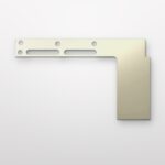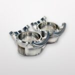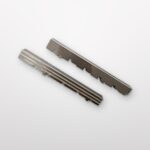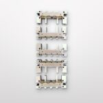

Punches, die inserts, comb-type locating inserts and other wire EDM parts are defined mainly by their two-dimensional profile. A punch tip that is slightly out of shape, a slot that is a few microns too narrow or a corner radius that does not match the drawing can stop a die from cutting cleanly or a fixture from locating parts correctly. Many of these features are small, close together and difficult to reach with a contact probe. A profile projector, also called an optical comparator, is one of the most practical ways to check them.
This article explains how a profile projector works, which features it is used to inspect on tooling components, and what buyers can put on the drawing and in the RFQ so that the inspection results are meaningful.
How a Profile Projector Works
A profile projector magnifies the outline of a part and projects it onto a large screen, where it can be measured or compared with a reference drawing.
- Contour (transmitted) illumination: light from below the stage is collimated and passes around the part. The part blocks the light, so its edges appear on the screen as a sharp silhouette. This is the main method for checking outer profiles, slots and through features.
- Surface (episcopic) illumination: light is directed onto the top face of the part through the projection optics, so features that do not pass through the part, such as markings or face details, can be viewed.
- Projection lens: interchangeable lenses set the magnification, for example 10x, 20x or 50x. At 50x, a 0.02 mm deviation on the part appears as 1 mm on the screen, which makes small form errors easy to see.
- Screen and crosshair: the ground-glass screen carries reference lines, usually a crosshair, used to pick up edges. The screen can be rotated for angle measurement.
- X-Y stage and digital counter: the part sits on a glass stage that moves in X and Y. Linear scales measure the stage travel and a digital counter displays the X and Y position.
- Digital protractor: measures the rotation of the screen, so that angles between edges can be read directly.
The magnified field of view is the screen diameter divided by the magnification. On a projector with a 300 mm screen, for example, a 10x lens shows a field about 30 mm wide, while a 50x lens shows about 6 mm. Higher magnification is chosen for small radii, narrow slots and sharp cutting edges; lower magnification for larger profiles that need to be seen in one view.
Measurement Methods
Coordinate measurement with the X-Y stage
For linear dimensions, the operator aligns one edge of the part with the crosshair, zeroes the counter, moves the stage until the opposite edge reaches the crosshair and reads the distance from the counter. Because the reading comes from the stage scales, this method does not rely on the magnification of the lens; the magnification only makes the edge easier to set accurately. It is used for slot widths, tooth widths, step widths, hole positions and distances between features.
Angle measurement with the protractor
To measure an angle, one line of the crosshair is aligned with the first edge, the protractor is zeroed, and the screen is rotated until the same line lies along the second edge. The protractor then displays the included angle. Typical applications are punch tip angles, wedge and cam angles, chamfers and draft on small profiles.
Overlay chart comparison
An overlay chart is a drawing of the nominal profile at the same scale as the lens, for example 20:1 or 50:1, usually with lines showing the upper and lower tolerance limits. The chart is placed on the screen and aligned to reference features of the part. If the projected profile stays between the tolerance lines along its whole length, the profile is within tolerance. Charts are produced from the customer’s CAD data, which makes this method well suited to complex outlines specified with a profile tolerance (profile of a line). It shows the whole contour at once, so local deviations such as a flat spot on a radius or a step at a wire EDM re-entry point are immediately visible.
Radii and arcs
Corner radii can be compared with radius gauge lines on an overlay chart, or measured by taking three or more points on the arc with the X-Y stage and calculating the radius and centre. The same point method is used for the diameter and position of small holes and arcs.
What Profile Projectors Are Used to Inspect on Tooling Components
In a toolroom that makes stamping die and fixture components, the profile projector is typically used for the following parts:
- Stamping punches: piercing and forming punch profiles, tip shape and corner radii
- Die inserts and die buttons: the profile of the die opening on parts thin enough to transmit light
- Wire EDM components: comb-type locating inserts, slotted locating blocks and shaped inserts
- Small precision parts: blades, wedges, angle punches and the tips and chamfers of locating pins
- Mold components: the end profiles of core pins and small inserts
- Reground punches: rechecking the cutting profile and size after sharpening
The features most often checked are:
- Profile against the drawing, using an overlay chart with tolerance bands
- Linear dimensions between edges, such as slot width, tooth width and step width
- Pitch of teeth and slots, both the individual pitch and the cumulative pitch over the full length
- Angles of inclined faces, cutting edges and chamfers
- Radii and arcs, including whether internal corners have the radius specified on the drawing
- Position and diameter of small holes and arcs in thin parts
- Symmetry, for example whether a punch tip is centred on its axis
- Edge condition: burrs, chipping, wire EDM re-entry marks and rounding of cutting edges
For wire EDM parts in particular, internal corners are a frequent point of discussion. An internal corner cut by wire EDM always has a radius at least equal to the wire radius plus the spark gap. If a sharp internal corner is required, it should be agreed at the drawing review stage, and the profile projector is then used to confirm the radius actually produced.
Preparing Parts for Reliable Readings
- Clean and deburr: oil, chips or a burr on the edge become part of the silhouette and change the reading.
- Orient the part correctly: the measured edges should be parallel to the light path, so that the silhouette shows the true profile. Flat parts lie on the stage glass; pins and round parts are held in a V-block or holder.
- Square the part to the stage: before measuring, a reference edge is aligned with the X axis using the crosshair and the protractor, so that X and Y readings correspond to the drawing coordinates.
- Use a consistent edge criterion: the crosshair is set on the edge in the same way at every point, so that readings are repeatable between operators.
- Check at temperature: parts and the instrument should be at room temperature, especially after grinding or wire EDM with coolant.
What to Include on the Drawing and in the RFQ
Optical inspection is most useful when the drawing makes clear what must be checked and against what reference:
- Datums for the profile, and which edges define the part’s orientation
- A profile tolerance for complex outlines, or clearly dimensioned critical features
- Corner radii, including the largest acceptable internal radius on wire EDM profiles
- Pitch requirements, stating whether the tolerance applies to individual or cumulative pitch
- Edge requirements, such as sharp cutting edges or a maximum burr height
- CAD data (DXF or STEP) so that an overlay chart can be prepared from the nominal geometry
- The inspection record required, for example a dimensional report or a first article inspection report
Our guide to first article inspection reports explains what such a report usually contains, and our article on wire EDM punches and die inserts covers the machining side of these components.
Inspection at SkyPu
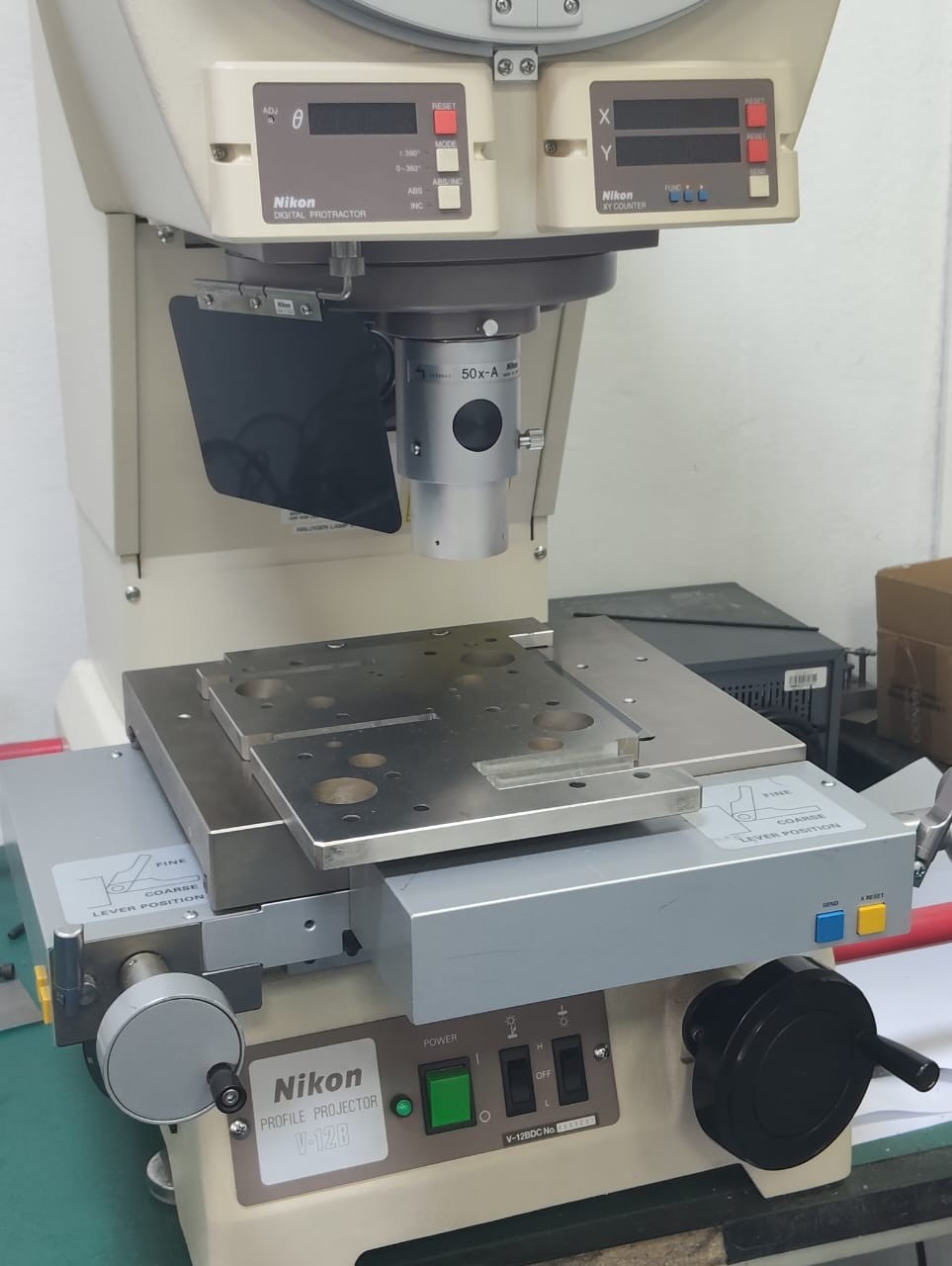
At SkyPu, we manufacture stamping die components, precision mold components and fixture parts to customer drawings, using CNC milling, wire EDM, sinker EDM and surface grinding. Profiles, angles and small features of punches, inserts and wire EDM parts are checked on a Nikon V-12B profile projector fitted with a Nikon digital protractor, a Nikon XY counter and a 50x projection lens.
The same inspection area also includes:
- Nikon MM-400 measuring microscope with an X-Y stage and digital counter, used for small features that are viewed from above, such as edges, small holes and details on the top face of a part
- TESA-hite 400 electronic height gauge on a granite surface plate, used for heights, steps and the position of features measured from a reference face
- Nikon Digimicro MFC-101 digital length gauge on an MS-11C stand, used for thickness and height measurement of small parts, punches and ground inserts


Dimensional reports are available on request.
If you have punches, inserts or wire EDM parts with critical profiles, send us your drawing with the material, quantity and tolerance requirements, and our team will review it and reply with a quotation.