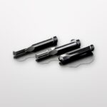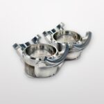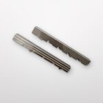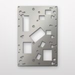

For moldmakers, injection molders and OEM tooling teams, custom core pins are small components with an outsized effect on an injection mold. Their geometry can form internal holes, ribs, bosses, threads, vents, and other features in the molded part. When a core pin wears, bends, chips, or no longer matches an engineering revision, the replacement must fit the existing mold and reproduce the intended plastic feature—not merely match one nominal diameter.
This RFQ guide helps industrial buyers source custom core pins from a China-based supplier. It explains the drawings, material specifications, mating requirements and inspection details a supplier needs to review manufacturability, select the required processes, and quote with fewer clarification cycles.
Quick Answer: What Should a Core Pin RFQ Include?
For an accurate quotation, provide a controlled 2D drawing and 3D model when available, plus the material grade, hardness, heat treatment, coating, quantity, target delivery date, critical tolerances, surface finish, inspection requirements, and information about the mating mold components. For replacement pins, identify the tool number, component number, drawing revision, and failure or wear condition.
Standard Core Pin or Custom Core Pin?
Standard catalog pins can be a practical choice when the required diameter, head style, length, material, and hardness already match the mold design. Custom manufacturing becomes relevant when the pin includes a nonstandard profile, multiple diameters, flats, grooves, threads, shutoff geometry, a special tip, a small cooling feature, an unusual material, or dimensions that must match an existing assembly.
Do not assume that “close enough” catalog dimensions are interchangeable. A difference in head thickness, transition radius, working length, fit, or surface condition can affect assembly, alignment, venting, molded-part dimensions, and service life.
1. Provide a Controlled Drawing and Model
A neutral 3D file such as STEP or Parasolid helps communicate the complete geometry. A dimensioned 2D drawing should control the requirements that cannot be inferred safely from the model, including:
- Nominal dimensions and individual tolerances
- Datum references and geometric tolerances
- Material grade and condition
- Hardness range and heat-treatment requirements
- Surface roughness and polishing requirements
- Coating type, thickness, and masked areas
- Threads, reliefs, edge conditions, and transition radii
- Inspection and certification requirements
State the measurement units clearly. If the customer’s drawing is in inches, the supplier should not silently convert and round critical dimensions. Keep the controlled requirement in the original units and show metric equivalents only as reference.
2. Identify the Features That Are Actually Critical
Applying the tightest tolerance to every dimension increases manufacturing and inspection cost without necessarily improving mold performance. Mark the features that control fit, alignment, molded-part geometry, sealing, or movement.
Typical critical characteristics may include the working diameter, concentricity between stepped diameters, straightness over the working length, shoulder location, head thickness, tip profile, and position of flats or other anti-rotation features. The correct datum strategy should reflect how the pin is located in the mold and how the molded feature functions.
Useful Metric and Inch References
| Metric value | Approximate inch value | Purchasing note |
|---|---|---|
| 0.10 mm | 0.0039 in | Often visible in fit or molded-part dimensions; specify function |
| 0.01 mm | 0.0004 in | May require controlled finishing and inspection |
| 0.005 mm | 0.0002 in | Confirm geometry, material condition, and measurement method |
| 0.001 mm | 0.00004 in | Reserve for selected critical features after engineering review |
SKYPU MOLD can review selected critical features down to ±0.001 mm (approximately ±0.00004 in), depending on the feature size, geometry, material, heat treatment, finishing sequence, measurement environment, and inspection method. This value should not be applied as a blanket tolerance to the complete part.
3. Specify Material, Hardness, and Heat Treatment
Material selection depends on the molding resin, operating temperature, corrosion risk, surface requirement, pin geometry, unsupported length, expected cycle count, and likely failure mode. Specify the exact material grade instead of writing only “tool steel” or “stainless steel.”
If an alternative grade is acceptable, require approval before substitution. Similar materials can differ in heat-treatment response, toughness, corrosion resistance, polishability, and dimensional stability. Also state whether the hardness requirement applies to the complete component or only to a treated surface.
For a replacement pin, tell the supplier why the previous component failed. Wear, bending, chipping, corrosion, galling, and plastic adhesion point to different design and material considerations. Changing to a harder material alone does not correct misalignment, insufficient support, sharp stress concentrations, or an unsuitable surface condition.
4. Define the Complete Geometry
Core pin drawings should define more than the working diameter and overall length. Depending on the design, also specify:
- Head diameter, head thickness, and seating face
- Shoulder location and transition radii
- Tip angle, spherical radius, flat, or molded profile
- Reliefs, undercuts, grooves, or vent flats
- Threads and thread class
- Anti-rotation flats or drive features
- Internal cooling holes or cross-holes, when required
- Permitted edge break and whether sharp edges are functional
Avoid undefined “sharp” internal corners when a functional radius is acceptable. If a sharp transition is required, identify why it matters so the supplier can evaluate grinding, EDM, wire EDM, or another suitable process.
5. State Surface Finish and Coating Requirements
Surface finish can affect part release, plastic adhesion, wear, sealing, and the appearance of the molded feature. Mark which surfaces require grinding, polishing, texturing, or another controlled finish. Do not apply a fine finish to hidden mounting surfaces unless the function requires it.
For coated pins, specify the coating, target thickness, dimensional condition, and masked areas. A buyer should clarify whether final dimensions apply before or after coating. Coating thickness may be small, but it matters when the fit or working diameter has a close tolerance.
6. Define Inspection Before Production Starts
The drawing and purchase order should identify the required inspection records. Depending on the application, the package may include a dimensional report, material certificate, hardness record, coating certificate, or a full inspection report.
Agree on the inspection datum and method for close-tolerance features. A long, slender pin may produce different results depending on support, measurement force, temperature, and instrument. If the customer requires a specific gauge, CMM strategy, roundness measurement, or measurement temperature, include it in the RFQ rather than introducing it after production.
7. Include Replacement and Urgency Information
For an urgent replacement, provide the mold or tool number, component number, revision, quantity, requested delivery date, and photographs of the worn or failed component. If a matching spare is available, dimensional data from that qualified component can help confirm the drawing.
Do not copy wear dimensions blindly. The damaged pin may be undersize, bent, chipped, polished by service, or altered during previous maintenance. The intended mold dimension and molded-part requirement should control the replacement whenever reliable design information is available.
Core Pin RFQ Checklist
- 2D drawing and 3D model
- Original units: mm or in
- Tool number, part number, and revision
- Exact material grade and approved alternatives
- Hardness, heat treatment, and coating
- Critical dimensions, datums, and geometric tolerances
- Surface finish and polishing requirements
- Quantity and expected repeat demand
- Inspection reports and certificates
- Required delivery date and shipping destination
- Failure details for a replacement component
Questions to Ask a Core Pin Supplier
- Which operations will be used for the critical features?
- Will heat treatment occur before or between finishing operations?
- How will long, slender geometry be supported and inspected?
- Can the supplier provide the required material and inspection records?
- Which tolerances require engineering confirmation before quotation?
- How will precision surfaces and tips be protected during shipment?
For related manufacturing capabilities, review our precision mold components manufacturing page. Buyers preparing a broader tolerance specification can also read CNC Machining Tolerances: How to Specify Them for an Accurate Quote and learn more about our manufacturing and quality approach.
Request a Custom Core Pin Quote from SkyPu
For new tooling, replacement components and repeat purchasing, send your drawing, material, quantity, critical tolerances, finishing requirements, and target delivery date to Lily@ksskypu.com. SKYPU MOLD will review the complete requirement before confirming manufacturability, price, and lead time.
Upload Drawings for a Core Pin Quote
Still clarifying the specification? Send a quick inquiry; file upload is optional in the short inquiry form.