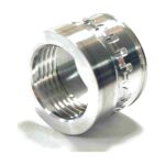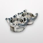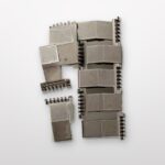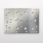

Replacement punch and die components are often sourced under time pressure, but a fast order is only useful when the new component fits the existing tooling and performs as intended. A worn punch, chipped die insert, damaged pilot, or cracked forming component may look straightforward to copy, yet wear, regrinding, heat-treatment movement, coating thickness, and undocumented engineering changes can make the removed part different from its original design.
This RFQ guide is for stamping engineers, toolroom managers, maintenance teams, and industrial buyers sourcing replacement components for progressive dies, compound dies, and other metal stamping tooling. It explains what information a supplier needs to review manufacturability, price, inspection scope, and delivery without relying on unsafe assumptions.
1. Identify the Component and Its Function
Begin with the component name, tool number, component number, drawing revision, and its function in the die. A supplier needs to know whether the part cuts, forms, locates, strips, guides, supports, or resists wear because the function affects material selection, edge preparation, dimensional priorities, and inspection.
- Cutting punch or die insert: cutting profile, punch-to-die relationship, edge condition, and shear are usually critical.
- Forming punch or forming insert: working profile, blend radii, surface finish, and orientation can control the stamped form.
- Pilot: working diameter, lead geometry, concentricity, and location relative to the holder affect strip registration.
- Stripper insert or pressure pad: clearance, bearing surfaces, spring or pressure relationships, and release behavior matter.
- Guide or wear component: fits, parallelism, surface condition, lubrication, and mating-part information may be essential.
If several components failed together, identify the complete set. Replacing one part without understanding its mating punch, die, retainer, guide, or stripper relationship may reproduce the same failure.
2. Send the Controlled Drawing and 3D Model
The preferred starting point is a released 2D manufacturing drawing and a matching 3D CAD model. The drawing should control tolerances, datums, material, hardness, heat treatment, coating, surface finish, edge condition, and inspection notes. The 3D model helps communicate complex geometry but should not replace the drawing where manufacturing requirements are not embedded in the model.
Include the current revision and explain any shop-floor changes that were made after the drawing was released. If the replacement must fit an existing assembly, mark the mating features and provide the relevant assembly dimensions or mating-component data.
SkyPu commonly reviews STEP, IGES, X_T, DWG, DXF, and PDF files. See the stamping die components service page for current manufacturing and RFQ details.
3. Do Not Treat a Worn Part as the Nominal Design
When the original drawing is unavailable, a physical sample can provide useful evidence, but it may not represent the intended nominal geometry. Cutting edges may have been sharpened, working diameters may be worn, coating may be missing, and previous repairs may have changed the part.
If a sample must be used, provide as much operating information as possible:
- How long the component was in production and the approximate stroke count, if known
- Whether the component was previously reground, welded, polished, or recoated
- The failure mode: abrasive wear, chipping, breakage, galling, bending, pickup, or loss of size
- The stamped material grade, thickness, and coating condition
- Photographs of the failed area and the component’s installed orientation
- Known-good dimensions or mating-part measurements from the toolroom
The buyer and supplier should agree which dimensions will be copied from the sample, which will be reconstructed from mating geometry, and which still require engineering approval. That decision should be documented before manufacturing begins.
4. Specify Punch-to-Die Clearance Clearly
For cutting components, clearance affects cutting force, edge condition, burr, tool load, and tool life. Do not assume that the supplier will calculate clearance from a generic percentage. The appropriate value depends on the stamped material, material thickness, required edge quality, tool design, and process conditions.
State whether the drawing dimension represents the punch size, die opening, clearance per side, or total clearance. Use one unit system consistently and include the alternate unit only as a reference. For example, 0.025 mm is approximately 0.001 in, while 0.0025 mm is approximately 0.0001 in; a misplaced decimal can create a major tooling error.
If punch and die components are ordered from different suppliers, identify the controlled master dimension and the intended relationship between the two parts. When possible, source and inspect the mating set together.
5. Define Material, Hardness, Heat Treatment, and Coating
Specify the exact material grade rather than writing only “tool steel” or “carbide.” Include the applicable standard, approved equivalents, delivery condition, target hardness range, heat-treatment method, cryogenic treatment if required, and coating specification.
SkyPu’s stamping-die component capabilities include customer-specified tool steels, high-speed steels, and selected tungsten-carbide grades. Material selection should reflect the stamped material, sheet thickness, production volume, wear mechanism, impact load, required edge life, and maintenance strategy. A material that provides high wear resistance in one application may be too brittle for another.
- State whether dimensions apply before or after heat treatment and coating.
- Define grinding or EDM stock when the buyer supplies semi-finished blanks.
- Identify surfaces that must remain uncoated or require masking.
- Specify edge preparation, polishing direction, and surface-roughness requirements.
- Request material, hardness, heat-treatment, or coating certificates when required.
A coating name alone is not enough when the finished size is critical. Confirm whether the coating thickness is included in the final dimension and how the coated surface will be inspected.
6. Mark the Features That Control Interchangeability
A replacement component must often install without hand fitting. Identify the datums, locating diameters, dowel holes, mounting faces, shank or head geometry, keyways, screw locations, and orientation features that control interchangeability.
Use geometric tolerances where they communicate function more accurately than independent plus/minus dimensions. For example, concentricity or runout may matter between a punch working diameter and its mounting shank, while flatness and parallelism may control a die insert’s seating and cutting relationship.
Selected critical features may be reviewed for tolerances as tight as ±0.001 mm (approximately ±0.00004 in), depending on geometry, material, heat treatment, feature size, process sequence, and inspection method. This is not a standard tolerance for every dimension. For practical guidance, read How to Specify CNC Machining Tolerances for an Accurate Quote.
7. Define Edge, Surface, and Orientation Requirements
Replacement tooling often fails at the working surface rather than at a mounting dimension. Specify the condition required at the cutting or forming area:
- Sharp edge, controlled hone, chamfer, or radius
- Shear angle or stepped cutting geometry
- Forming radius and blend requirements
- Polish direction and surface-roughness limit
- Relief, back taper, land length, and transition geometry
- Orientation marks and handed features
Where a profile is difficult to describe, include a section view, enlarged detail, or annotated image. Avoid notes such as “polish as needed” when the surface has a measurable functional requirement.
8. Agree on the Inspection Plan Before Production
List the dimensions and characteristics that require recorded results. The inspection method should match the feature and tolerance, and measurements should be taken at the correct manufacturing stage.
- Incoming material verification and certificate review
- In-process checks after machining, EDM, heat treatment, or grinding
- Hardness verification at the agreed location
- Final dimensional inspection from the drawing datums
- Profile, edge, surface-finish, and coating verification when specified
- Critical-dimension or full inspection report, based on project risk
For an interchangeable replacement, consider verifying the new component against a mating component, fixture, approved master, or assembly requirement when appropriate. State whether inspection data must be approved before shipment.
9. Plan for Delivery Without Damaging Precision Surfaces
Urgent replacement tooling still requires suitable packaging. Cutting edges, polished surfaces, carbide parts, threads, and close-fit diameters should be protected from impact, contact, corrosion, and contamination during international transportation.
Include the required delivery date, destination, shipping method, Incoterm, and any split-shipment or first-piece requirement in the RFQ. Ask the supplier to separate manufacturing lead time from transportation time and identify material or outside-processing constraints before the order is placed.
Replacement Punch and Die Component RFQ Checklist
Use this checklist when requesting a quotation:
- Tool number, component number, component name, and drawing revision
- Released 2D drawing and matching 3D CAD model
- Function: cutting, forming, piloting, stripping, guiding, supporting, or wear control
- Stamped material grade, thickness, and coating condition
- Punch-to-die clearance definition and mating-component information
- Tool material, approved equivalent, hardness, heat treatment, and coating
- Critical datums, fits, geometric tolerances, and final dimensional condition
- Cutting-edge, forming-surface, polish, and surface-finish requirements
- Quantity, including spares and first-article quantity
- Inspection report, material certificate, hardness record, and coating certificate requirements
- Failure description, photographs, maintenance history, and sample condition
- Packaging, marking, target delivery date, destination, and shipping terms
Questions to Ask a Replacement Tooling Supplier
- Which dimensions or requirements need clarification before quotation?
- Which operations will be used: CNC machining, grinding, EDM, wire EDM, heat treatment, and coating?
- How will heat-treatment movement and finishing allowance be controlled?
- How will the critical features be measured and reported?
- Can the supplier preserve the approved process and revision for repeat orders?
- What information is still required to confirm delivery?
Frequently Asked Questions
Can a replacement punch or die insert be made from a physical sample?
A sample can provide useful dimensional and failure evidence, but wear, regrinding, repairs, and coating loss may make it different from the nominal design. A controlled drawing is preferred. If no drawing exists, the buyer and supplier should document which dimensions are copied, reconstructed, or awaiting engineering approval.
What information is needed for punch-to-die clearance?
Provide the stamped material, material thickness, punch size, die opening, and the intended clearance. Clearly state whether clearance is per side or total. Also define which component controls the final stamped feature.
Should dimensions apply before or after coating?
The drawing should state the required condition. When coating thickness affects a close fit or working dimension, identify the coated surfaces and confirm that the final dimension includes the coating.
Can SkyPu manufacture carbide punches and die inserts?
SkyPu machines selected tungsten-carbide grades for punches, die inserts, and wear-resistant tooling components. Geometry, grade, edge condition, surface finish, mating relationship, and inspection requirements should be included in the RFQ.
Request a Review for Replacement Stamping Tooling
SkyPu coordinates CNC machining, grinding, EDM, wire EDM, heat treatment, and finishing for custom stamping die components. Send your released drawing, 3D model, material, hardness, coating, quantity, critical dimensions, inspection requirements, and delivery target to Lily@ksskypu.com.
For special confidentiality requirements, contact Lily before sending files. You can also use the SkyPu contact and RFQ page, review our manufacturing and quality background, or explore related CNC precision machining services.