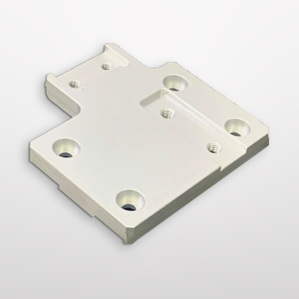
Most tooling plates are held together by socket head cap screws, so nearly every die plate, punch holder, stripper plate and fixture plate has counterbored holes and tapped holes on it. These holes look simple, but a short callout can still leave room for guesswork. If the counterbore is too shallow, the screw head sits proud and can hit the mating plate. If the thread is too short, the screw strips. If the tap drill is not deep enough, the tap bottoms out and breaks. This article explains how to call out counterbored and tapped holes on a tooling plate drawing, with standard sizes, depth rules and example callouts.
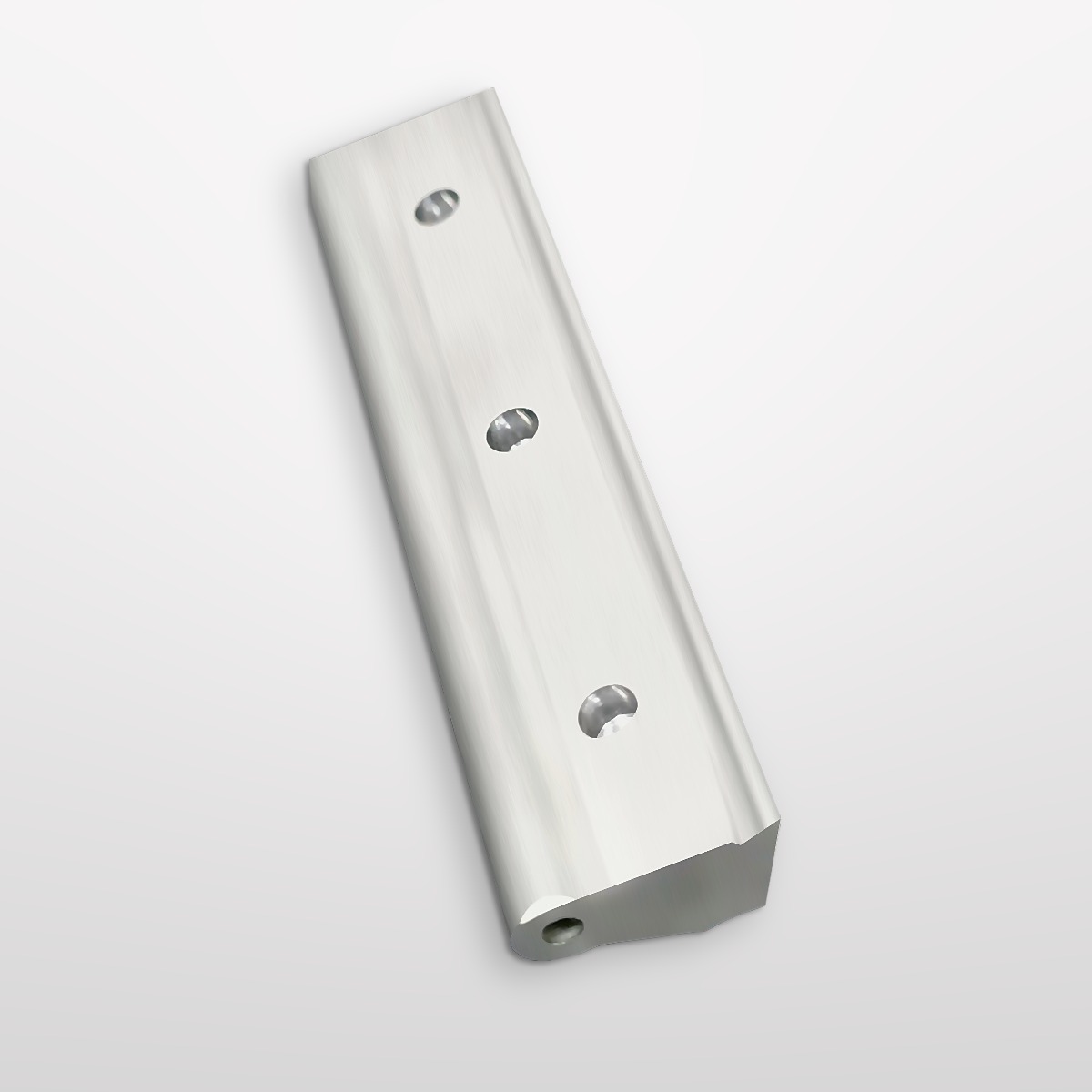
Screws Clamp, Dowels Locate
Before sizing any hole, it helps to separate two jobs. Screws pull the plates together. Dowel pins set the position. A clearance hole for a screw is deliberately larger than the screw, so the screw cannot locate the plate accurately. If a plate has to sit in an exact position, for example a die plate under a punch holder, use dowel pins in reamed holes for location and keep the screw holes as clearance holes. This also tells the machinist which holes need a tight position tolerance and which do not.
Counterbored Holes for Socket Head Cap Screws
A counterbored hole has two parts: a clearance hole for the screw shank, and a larger, flat-bottomed bore that lets the screw head sit below the surface. Three values define it: the clearance hole diameter, the counterbore diameter and the counterbore depth.
Clearance hole. ISO 273 gives three series of clearance holes for metric screws: fine, medium and coarse. The medium series suits most tooling plates. The fine series gives less play, and the coarse series gives more room for misalignment between plates. JIS B 1001 uses the same values as grades 1, 2 and 3. The table below lists them from an NBK technical data sheet (JIS B 1001).
Counterbore diameter and depth. MISUMI’s technical data for hexagon socket head cap screws, based on JIS B 1176, lists a counterbore diameter and two counterbore depths for each size (MISUMI). The depth must be enough for the screw head to sit below the plate surface.
| Screw | Clearance hole, ISO 273 fine / medium / coarse (mm) | Counterbore Ø (mm) | Counterbore depth (mm) |
|---|---|---|---|
| M3 | 3.2 / 3.4 / 3.6 | 6.5 | 2.7–3.3 |
| M4 | 4.3 / 4.5 / 4.8 | 8 | 3.6–4.4 |
| M5 | 5.3 / 5.5 / 5.8 | 9.5 | 4.6–5.4 |
| M6 | 6.4 / 6.6 / 7 | 11 | 5.5–6.5 |
| M8 | 8.4 / 9 / 10 | 14 | 7.4–8.6 |
| M10 | 10.5 / 11 / 12 | 17.5 | 9.2–10.8 |
| M12 | 13 / 13.5 / 14.5 | 20 | 11–13 |
Treat the table as a starting point and check it against the screws you actually use and your own design standard. Two points are specific to tooling plates:
- Plates that will be reground. Die plates, die inserts and stripper plates are often surface ground again when they are sharpened or repaired. Every regrind makes the plate thinner and brings the screw head closer to the surface. If a plate will be reground, add the regrind allowance to the counterbore depth so the head still sits below the face after the last grind.
- Counterbores from the back side. If the screw goes in from the bottom of the plate, state which face the counterbore is on. A section view or a note such as “C’BORE FROM BACK” removes any doubt.
Have a plate drawing ready? Send it to us with material, hardness and quantity, and we will reply with a price and lead time within 2 days.
Tapped Holes: Size, Class and Depth
Thread size and tolerance class
Give the full thread designation, not only the nominal size. For metric threads, that means the size, the pitch and the tolerance class, for example M6×1-6H. For common use, ISO 965 recommends tolerance class 6H for internal threads and 6g for external threads (Tameson). For Unified inch threads, Class 2 is the most common, and the letter B marks an internal thread, as in 1/4-20 UNC-2B (Tameson). If you use a fine pitch, write the pitch: M8×1 is a different tap from M8×1.25.
Thread depth
The thread must be deep enough for the screw to carry its load. A commonly cited minimum thread engagement is about 1 times the nominal diameter in steel and about 2 times the nominal diameter in aluminum (Nord-Lock). For softer materials or special alloys, those values may not be enough and the engagement should be calculated. On the drawing, give the depth of the full thread, not the depth of the drill.
Drill depth for blind holes
A tap has a chamfer at its tip, and the chamfer does not cut a full thread. In a blind hole, the drilled hole must therefore be deeper than the full thread. Kennametal recommends that the drill depth allow for the full thread length, the tap chamfer and at least one extra pitch at the bottom for spindle over-travel and chips (Kennametal Tech Tip 65). If the plate is thin or the hole is close to the back face, check that the drill point will not break through. If there is no room for the extra depth, tell the supplier so a bottoming tap or thread milling can be used.
Threads in hardened plates
Tapping hardened tool steel is difficult, so threads in hardened plates are usually cut before heat treatment. Heat treatment can change the thread slightly. If a thread is critical, say so on the drawing, and agree with the supplier whether threads are checked with a thread gauge after heat treatment.
Hole Positions Across Several Plates
In a die, the same screw and dowel pattern often runs through several plates: the punch holder, the stripper plate, the die plate and the die shoe. If each plate is dimensioned from a different edge, small errors add up and the screws will not go in. Dimension the pattern on every plate from the same datums, and give the position tolerance relative to those datums. Our CNC machining tolerances guide explains how to set tolerances that are tight where they matter and economical elsewhere. Where plates must also be flat and parallel for stacking, see our article on surface grinding for tooling plates.
Example Callouts
The examples below use word notes. On a drawing you can use the standard counterbore and depth symbols instead. The depth symbol means the depth is measured to the bottom of the full-diameter part of the hole, not to the tip of the drill point (GD&T Basics).
| Feature | Example callout | What it tells the machinist |
|---|---|---|
| Counterbored hole for M6 socket head cap screws | 4X Ø6.6 THRU, C’BORE Ø11 × 6.5 DEEP | Medium-series clearance hole, head sits below the surface |
| Counterbore on the back face | 2X Ø9 THRU, C’BORE Ø14 × 8.6 DEEP FROM BACK | Which face to bore from |
| Blind tapped hole | 2X M6×1-6H × 12 DEEP, DRILL Ø5 × 16 DEEP | Full thread depth and the drill depth below it |
| Through tapped hole | 4X M8×1.25-6H THRU | Thread runs through the whole plate |
| Inch thread | 2X 1/4-20 UNC-2B × 0.38 DEEP | Size, threads per inch, class and depth |
The drill depths in the table are examples only. The right value depends on the tap you use and the room behind the hole.
Checklist Before You Send the Drawing
- Every tapped hole has a full designation: size, pitch if it is not coarse, tolerance class and full-thread depth.
- Blind tapped holes have a drill depth, or a note that the supplier may choose it within a stated limit.
- Every counterbore has a diameter and a depth, and the face it is on is clear.
- Counterbore depths include the regrind allowance on plates that will be sharpened or repaired.
- Screw holes are clearance holes, and location comes from dowel pin holes with their own tolerance.
- Hole patterns that run through several plates are dimensioned from the same datums.
- Material and hardness are stated, and critical threads in hardened plates are flagged.
- A 3D model is attached if you have one. Our guide to preparing CAD files for a quote lists what to include.
How We Machine Plates with Screw and Dowel Holes
At SkyPu, we make stamping die components and CNC machined parts to customer drawings, including die plates, stripper plates, punch holders and mounting plates. Holes, counterbores and threads are machined on our 8 CNC machining centers. Openings and shaped profiles are cut on our 18 wire EDM machines, including Sodick low-speed wire EDM, and flat faces are finished by surface grinding. Critical dimensions are checked with Nikon and TESA inspection equipment, and a dimensional report can be supplied on request. We machine to tolerances down to ±0.002 mm, and typical lead time is about one week, excluding shipping.
Preguntas frecuentes
What clearance hole should I use for an M6 socket head cap screw?
The ISO 273 medium series gives 6.6 mm for M6, which suits most tooling plates. The fine series gives 6.4 mm and the coarse series 7 mm. Remember that a clearance hole does not locate the plate; use dowel pins for that.
How deep should a counterbore be?
Deep enough for the screw head to sit below the surface. MISUMI lists 5.5–6.5 mm for M6 socket head cap screws. On plates that will be reground, add the regrind allowance.
How deep should a tapped hole be?
A commonly cited minimum thread engagement is about 1 times the screw diameter in steel and about 2 times in aluminum. In a blind hole, the drill must go deeper than the full thread to make room for the tap chamfer and chips.
Can you work from a 3D model without a full 2D drawing?
Yes, but threads are often not modeled in 3D. If you send only a model, list the thread size, class and depth for each tapped hole in a note or a separate table.
Need die plates, stripper plates or mounting plates made to drawing? Send your drawings with material, hardness and quantity, and we will reply with a price and lead time within 2 days.
Sources
- MISUMI technical data: Hexagon socket head cap screws, counterbore dimensions (JIS B 1176)
- NBK technical data: Diameter of clearance holes and counterbores for bolts and screws (JIS B 1001)
- Tameson: Thread tolerance chart
- Nord-Lock: The Experts, thread engagement in a tapped hole
- Kennametal Tech Tip 65: Tap chamfer length vs. tool life in threading
- GD&T Basics: Depth symbol