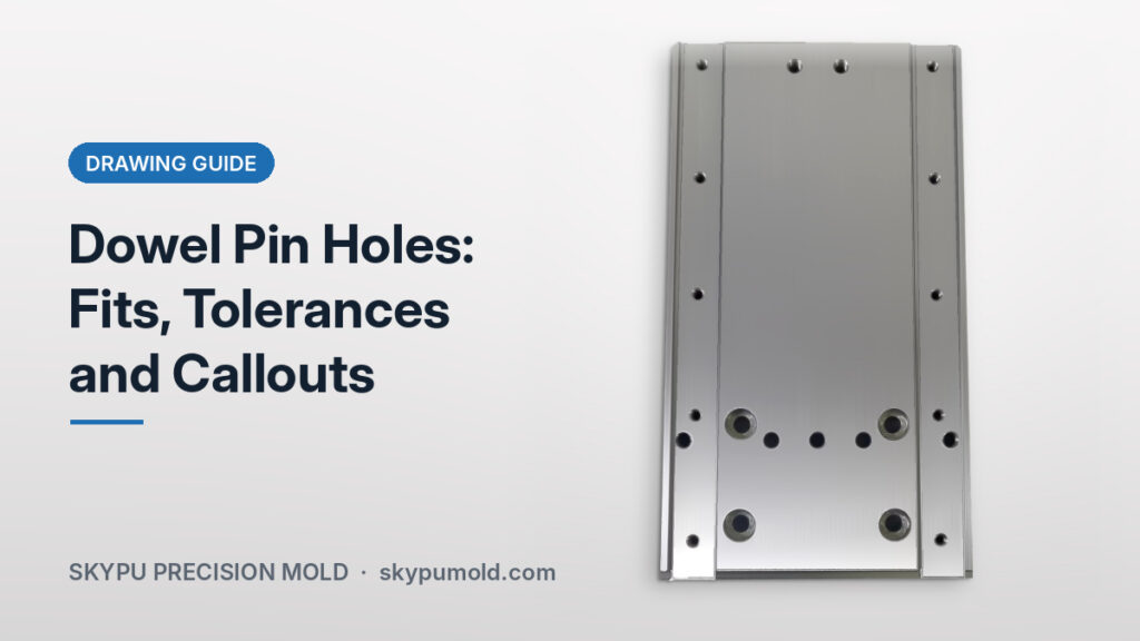
Dowel pin holes in tooling plates and fixtures are usually reamed to H7 and paired with hardened m6 pins, which gives a transition fit. The pin is normally tight in one plate and sliding in the mating plate, and fixtures that are loaded often use one round pin and one relieved pin. This article explains these fits, the hole tolerances behind them, and how to call out dowel holes clearly on your drawing.
Screws Clamp, Dowels Locate
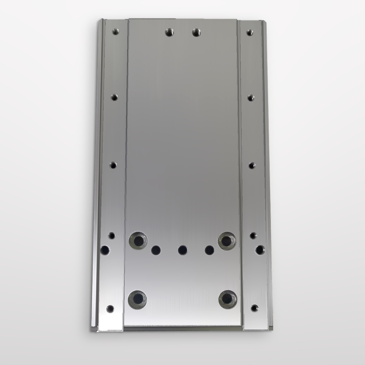
A clearance hole for a screw is deliberately larger than the screw, so a screwed joint can shift before the screws are tightened. A dowel pin fits its hole with almost no clearance, so it fixes the position. On a well-designed assembly, screws provide the clamping force and two dowel pins provide the location, so only the dowel holes need tight tolerances. We covered screw holes in our article on tapped and counterbored holes in tooling plates.
Pin Tolerance and Hole Tolerance
Metric hardened dowel pins are commonly ground to m6, and the hole is reamed or ground to H7. Elesa+Ganter notes that a dowel pin in an H7 location hole gives a transition fit (Elesa+Ganter). For a sliding fit, a g6 pin in an H7 hole is a common choice (Wevolver, ISO 286 H7 chart). The ISO 286 limits for common sizes are shown below, in micrometers (µm).
| Nominal size (mm) | Hole H7 | Pin m6 | Pin g6 |
|---|---|---|---|
| over 3 to 6 (e.g. Ø4, Ø5, Ø6) | 0 / +12 | +4 / +12 | −12 / −4 |
| over 6 to 10 (e.g. Ø8, Ø10) | 0 / +15 | +6 / +15 | −14 / −5 |
| over 10 to 18 (e.g. Ø12, Ø16) | 0 / +18 | +7 / +18 | −17 / −6 |
| over 18 to 30 (e.g. Ø20, Ø25) | 0 / +21 | +8 / +21 | −20 / −7 |
An m6 pin in an H7 hole can be slightly loose or slightly tight, which is why the fit is called a transition fit. The whole hole tolerance is only 12 to 21 µm, so dowel holes are drilled undersize and then reamed, bored or ground. SPIROL stresses that a reamer cannot correct a crooked or out-of-round drilled hole (SPIROL). If you use pins with a different tolerance, state the pin on the drawing so the hole can be matched to it.
Tight in One Plate, Sliding in the Other
A common arrangement is a firm fit in one plate and a sliding fit in the mating plate. The pin stays in the first plate, and the second plate can be lifted off and put back without forcing. If the pin is tight in both plates, the plates have to be pressed apart, which can damage the holes and the pin. You can achieve this with:
- Different hole tolerances: H7 in the retaining plate and a slightly larger hole in the mating plate. State both clearly.
- Two-tolerance or stepped pins: one diameter for the press fit, another for the sliding fit. With identical holes and a g6 pin, you cannot predict which plate the pin stays in (Eng-Tips).
- Bushings: for assemblies opened often, a hardened bushing takes the wear instead of the plate.
One Round Pin, One Relieved Pin
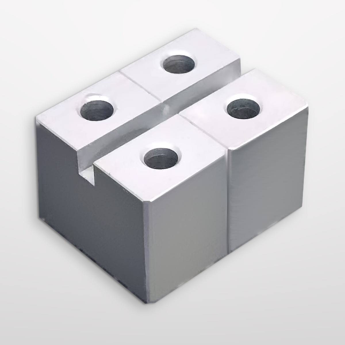
Two round pins in two tight holes only work if the hole spacing is exactly the same on both parts. Any difference makes the part hard to load or bends the pins. In fixtures that are loaded often, a common solution is one round pin and one diamond (relieved) pin. MISUMI recommends this combination because it eases insertion and compensates for small spacing errors, and it also recommends placing the two pins as far apart as possible (MISUMI). The round pin fixes the position; the diamond pin only stops rotation. A slot in the mating part instead of a second round hole works the same way.
Blind Holes, Through Holes and Removal
- Through holes let a pin be pressed out from the back, which helps on plates that are separated for maintenance or regrinding.
- Blind holes trap air and the pin cannot be pushed out from behind. Dowel pins with an internal thread can be pulled out, and versions with a side flat let air escape (Elesa+Ganter).
- Depth: give the depth of the reamed, full-diameter portion, not just the drill depth.
- Edge break: a small chamfer at the entry helps the pin start straight and keeps burrs from stopping the plates sitting flat.
Position Tolerance Between Dowel Holes
The size tolerance controls how the pin fits its own hole; whether two plates line up depends on hole position. Dowel holes in mating plates need a tight position tolerance from the same datums. A common practice is to machine the dowel holes in mating plates in one setup, or to jig-grind them, so their spacing matches.
Example Callouts
| Situation | Example callout |
|---|---|
| Through hole, transition fit with an m6 pin | 2× Ø8 H7 THRU, for Ø8 m6 dowel pin |
| Blind hole | 2× Ø8 H7 ▽12 (reamed depth), drill Ø7.8 ▽15 |
| Sliding fit in the mating plate | 2× Ø8 +0.016/+0.026 THRU, sliding fit on Ø8 m6 pin |
| Hole position | Position tolerance from the same datums on both plates, or “machine with mating plate” |
These are examples. In the sliding-fit example, the smallest hole (8.016 mm) is just larger than the largest m6 pin (8.015 mm), so the pin always slides. Whatever you choose, state the tolerance class, the full-size depth and the pin it has to fit.
Checklist Before You Send the Drawing
- Only the dowel holes have tight tolerances, and each has a tolerance class such as H7.
- It is clear which plate holds the pin and which plate slides on it.
- Fixtures loaded often use one round and one relieved pin, placed far apart.
- Blind holes have a reamed depth and a way to remove the pin.
- Mating plates use the same datums, or the holes are machined together.
How We Machine Plates with Dowel Holes
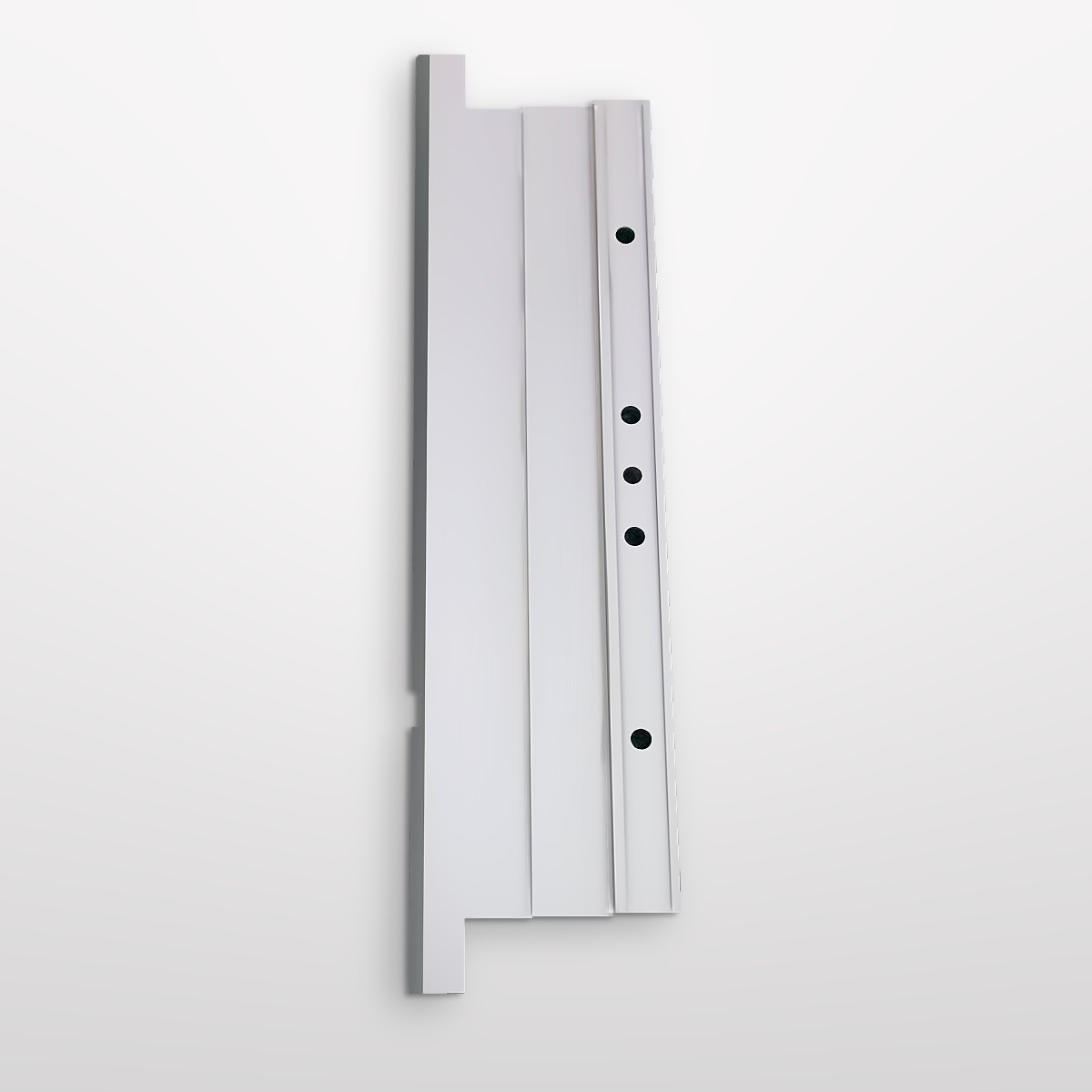
At SkyPu, we make stamping die components y CNC machined parts to customer drawings, including die plates, punch holders, fixture plates and fixture blocks. Holes and counterbores are machined on our 8 CNC machining centers, profiles are cut on our 18 wire EDM machines, including Sodick low-speed wire EDM, and flat faces are finished by surface grinding. Critical dimensions are checked with Nikon and TESA inspection equipment, and a dimensional report can be supplied on request. Selected features can be held to approximately ±0.002 mm. You can see examples in our CNC milling product cases y stamping tooling product cases.
Preguntas frecuentes
What hole tolerance should I use for a dowel pin?
H7 is the most common. With a hardened m6 pin it gives a transition fit. For a sliding fit, use a g6 pin or make the mating hole slightly larger, and state it on the drawing.
Why use a diamond pin instead of a second round pin?
Two round pins need the hole spacing to match exactly. A diamond pin only stops rotation, so it tolerates small spacing errors and makes loading easier.
How do I remove a dowel pin from a blind hole?
Use a pin with an internal thread and pull it out with a puller. Pins with a vent flat also let trapped air escape. Where possible, use through holes.
Need die plates, fixture plates or fixture blocks with dowel holes made to drawing? Send your drawings with material, hardness and quantity, and we will review it and reply with a price and lead time.
Sources
- Elesa+Ganter: Dowel pins DIN 7979 (internal thread, air vent flat, H7 location hole)
- Wevolver: H7 tolerance explained, ISO 286 hole tolerance charts
- MISUMI: Locating pins tutorial (round and diamond pins, pin spacing)
- SPIROL: Hole preparation for press-fit pins
- Eng-Tips: Discussion of dowel pin hole tolerances